|
|
|
|
PRINCIPLE of the PIPEPUMP invented and developed by David Parsons and Simon Farthing
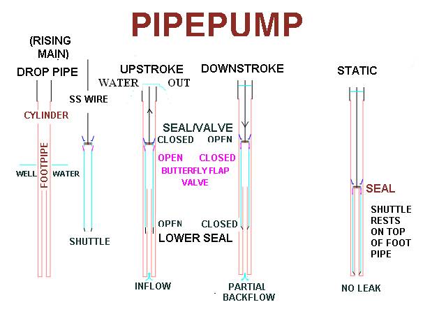
The Pipepump cylinder has an internal "footpipe" erected from a bushing at its end for about 1/2 the length of the cylinder and with OD about 1/2 its ID but no valves or seals. The plunger has a valve and seal mounted on top of a piece of pipe which has an annular bearing seal at the lower end that slides over the footpipe as the plunger is lowered. The inside top of the shuttle has a leather or rubber slug that can rest on the top of the footpipe and statically seal below the normal working stroke of the pump. On the outside below this closed top end of the shuttle is a simple rubber flap butterfly valve sealing over perforations.
On the upstroke the plunger top valve is closed and pushes the watercolumn depth H up and the butterfly side valve opens as well water is sucked in through it via the footpipe to fill the increase of height of the annular volume between the cylinder and the uncovered footpipe.
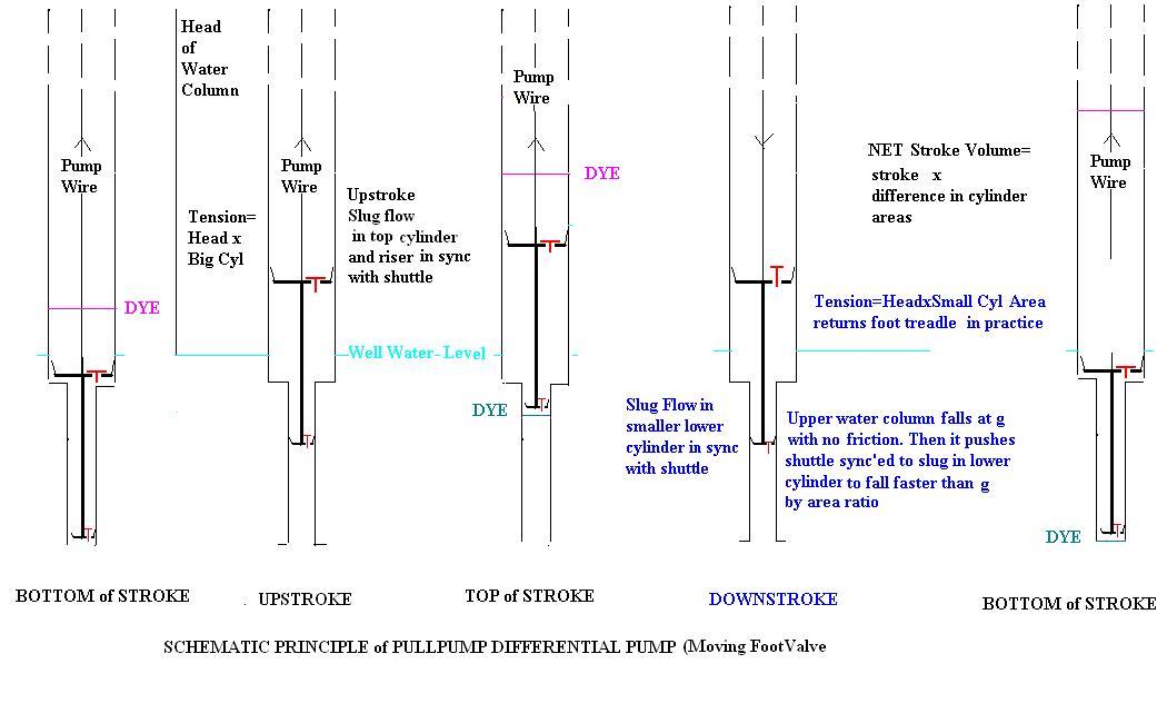
On the downstroke the butterfly valve closes and the water in the footpipe descends with the shuttle. The top valve is open as it drops through the water trapped between the footpipe and the cylinder. Because the annular cross-sectional area between them is say 3/4 of the cylinder above, the level above drops y/4 for every y the shuttle drops. Correspondingly there is a netdownwards pressure pH( g-y''/4) on the shuttle on an area equal to the footpipe outer crossectional area (where y'' is the shuttle downwards acceleration). This hydraulic return pressure can make the shuttle fall faster than g (in this caseup to 4 times) which it can never do under its own weight no matter how massive.
On conventional fixed footvalve pumps with no partial water column return, the limit on the gravity return of the pumprods required gearing of small windmills and prevented footpumps, since footpumping is best at pedalling speeds around the heart rate whereas handpumping synchronises with the slower breathing rate. The faster more powerful footpumping is now possible as well as transmitting the pull with continuous wire at longer strokes. A windrotor would need slightly increased counterbalancing of its crank with this pump.
The downstroke regression of the footpipe water backwashes any inlet filter there though only at 1/4 the upstroke velocity. Ample clearance should be left between the statically sealed shuttle and the bushing so that dirt suspended in the water column can settle harmlessly there.
For pressure pumping at the surface, pass a vinyl coated pump wire through another bearing seal, and install a check valve at the entry to a bladderless pressure tank and an air snifter valve immediately below it. Then the regression of the water column in the downstroke sucks air in at the top and then the upstroke delivers this 1/4 stroke air as well as the 3/4 stroke water to the tank where the air accumulates to smooth the waterflow in the exiting water delivery pipe, and can also be tapped (The pipepump and its applications are presented inside the wing'd pump video )
Alternatively the top valve and seal at the top of the shuttle can be separated so the output passes through the valve into a piston pipe to a pipe T handle at the surface with either downward output into a bucket or pressurised output through a flexible pipe on a push downstroke, Especially in the latter case the seal should be a double acting one. The central idea of the pipepump is so emphasised to be the elimination of the bottom footvalve in favour of the side flap valve on the shuttle which can be easily pulled to the surface for maintenance of all the moving parts. On newly drilled wells such as by Terry Waller’s Baptist method, the dropipe to allow maintenance of the footvalve can then be eliminated and the well casing itself used for the cylinder to get the maximum output for the size of the hole. The footpipe bushing is threaded for remote insertion into the casing filter joint after well conditioning.
If the shuttle is sprung or counterweighted to normally lift the water column, then conversely overpressuring the water column by a factor of 4 will depress the shuttle and achieve hydraulic transmitted pumping. This is the differential pumping principle behind the Awassa pump previously and independently invented by our helpful friend Larry Dillon, PEng..
also see Detailled Design of the Pipepump